Per-Instruction Dataflow
This page shows how data actually moves through the hardware once an instruction is dispatched. The figures below recast the block diagram from Top-Level Architecture through an instruction’s lens.
1. GEMM
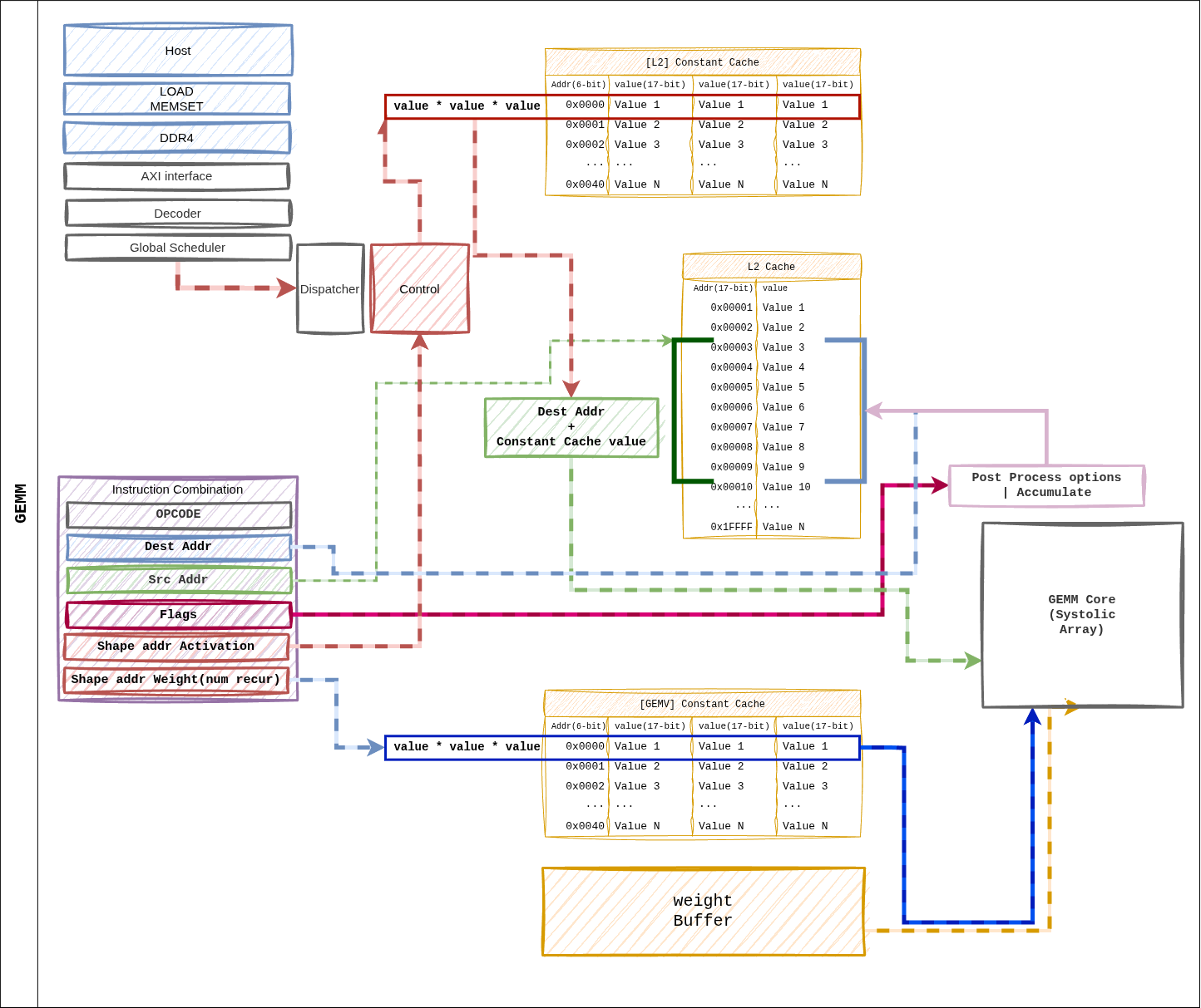
Figure 10 Figure 5. Dataflow when a GEMM instruction dispatches.
dest_addr and src_addr live in the L2 cache address space;
shape / size pointers index the Constant Cache.
Path Summary
Dispatcher reads
shape_ptr_addr/size_ptr_addrfrom the Constant Cache to obtain the tile parameters.Weight Buffer prefetches a tile’s worth of weights from the HP ports.
L2 cache
src_addrstreams activations into the systolic array.The array accumulates Weight Stationary → Accumulator → Post-Process.
The result is written back to L2 cache at
dest_reg.
2. GEMV
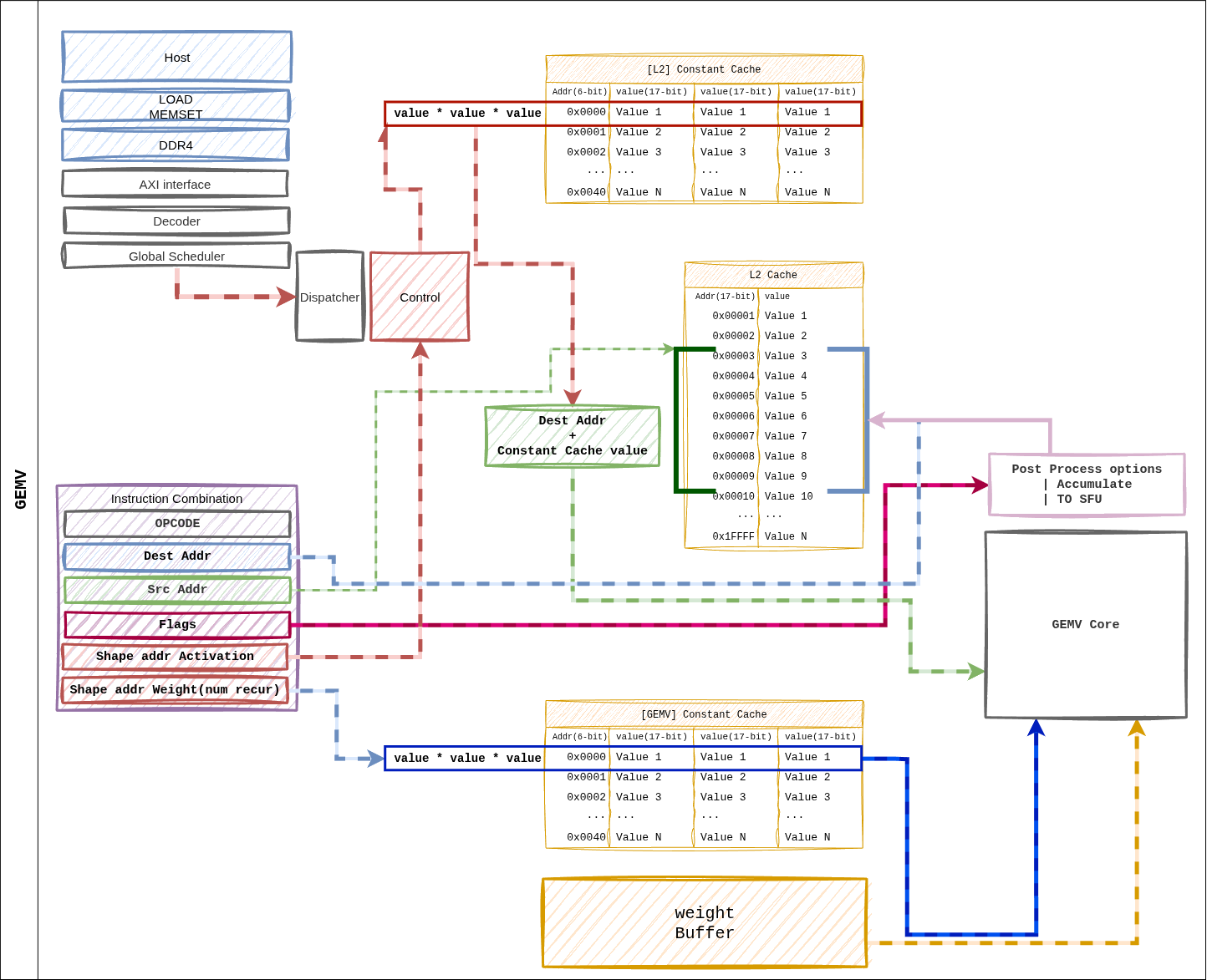
Figure 11 Figure 6. Dataflow for a GEMV instruction. Same ISA layout as GEMM, but weights are consumed in a Weight Streaming pattern, fanning out across 4 GEMV cores in parallel.
Path Summary
Dispatcher resolves pointers → per-core shape distribution.
Weight Buffer → 4 GEMV cores, streaming by row partition.
L2 cache → per-core L1 cache for activation preload.
32-lane LUT-based MAC inside each core + 5-stage reduction tree → scalar result.
Post-Process (scale, bias) → L2 cache or direct SFU FIFO.
3. MEMCPY
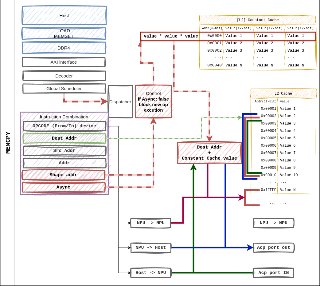
Figure 12 Figure 7. MEMCPY instruction. The from_device / to_device
combination supports host ↔ NPU and NPU ↔ NPU transfers.
Supported Combinations
from_device |
to_device |
Path |
|---|---|---|
1 (Host) |
0 (NPU) |
ACP → L2 cache write. Used for weight / input loads. |
0 (NPU) |
1 (Host) |
L2 cache → ACP. Returns output tokens / KV entries. |
0 (NPU) |
0 (NPU) |
Intra-L2 block move (on-device rearrangement). |
When async = 1, execution continues to the next instruction
immediately. The Global Scheduler tracks the completion fence.
4. MEMSET
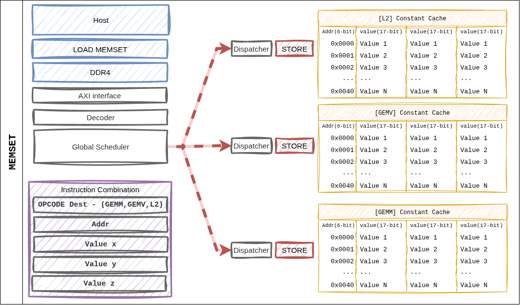
Figure 13 Figure 8. MEMSET writes directly from the Dispatcher into the Constant Cache — the only instruction that bypasses the L2 cache.
Characteristics
A single instruction can write up to three 16-bit values (
a,b,c) at once.Typical use: initialize the (M, N, K) tuple at the start of a layer, or inject weight / activation scale factors.
dest_cacheselects which cache bank is targeted (fmap_shape vs. weight_shape).
5. CVO (SFU)
CVO does not have a dedicated figure, but the path is:
Dispatcher
    │
    ▼
cvo_control_uop_t → SFU (single BF16 scalar pipeline)
                       ▲
                       │ L2 cache ``src_addr``  ─── input vector
                       │
                       ▼
                    function pipeline (CORDIC / LUT)
                       │
                       └─► L2 cache ``dst_addr`` / GEMV direct FIFO
Fast Path: if the SFU consumes the output of the preceding GEMV
immediately, src_addr is set to a special tag and the L2 round
trip is skipped. The Dispatcher’s dependency-tracking logic decides this
automatically.
6. Dependencies and Completion
Inter-instruction dependencies are resolved in the Global Scheduler via two checks.
Address hazard: read-after-write on dest / src L2 addresses.
Resource hazard: occupancy of the GEMM / GEMV / SFU resources.
Completion of an asynchronous instruction (async = 1) is collected
by the fsmout_npu_stat_collector block and reported to the host via
the AXI-Lite STAT_OUT register.