GEMV Core
The GEMV core handles the dominant operation during autoregressive
decoding — the matrix-vector product y = W x. In batch-1,
sequence-1 decoding, 85 – 98% of the FLOPs come from GEMV, which makes
GEMV throughput directly proportional to tokens-per-second.
Important
Running decoding on a 2D systolic array alone drops effective
utilization to 1/32 (only a single row is active). pccx v002 fixes
this with a dedicated 1D GEMV core placed alongside the GEMM
array; both paths share the same L2 cache, giving the architecture its
heterogeneous character.
1. Operands
GEMV’s inputs are an activation vector of length N and an N × N weight matrix.
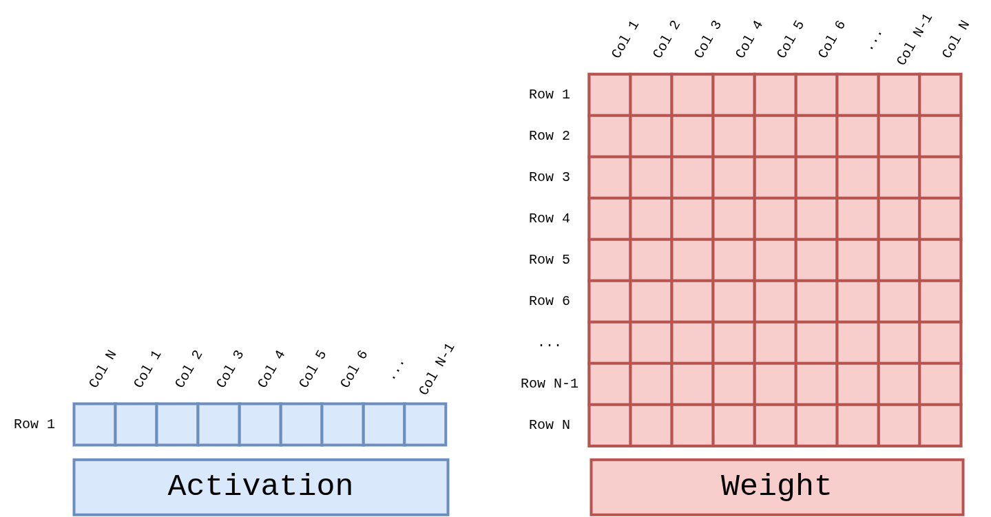
Figure 7 Figure GEMV-Operands. Activation is a 1 × N row vector, Weight is
an N × N matrix. Their inner product produces a new length-N output
vector. Both Attention’s Q·Kᵀ and FFN projections follow this
same shape.
2. Configuration
Parameter |
Value |
|---|---|
Per-core dimensions |
32 (K) × 1 (M) |
Number of cores |
4 total ( |
Per-core multiply width |
32 MAC / clk (INT4 × BF16, LUT-based pre-computation) |
Stage-1 accumulator DSPs |
16 DSP48E2 per core (32 partial products → 16 pair-sums) |
Reduction tree |
5 stages (32 → 16 → 8 → 4 → 2 → 1) |
Peak throughput |
32 MAC × 4 cores × 400 MHz = 51.2 GMAC/s |
3. Core Internals
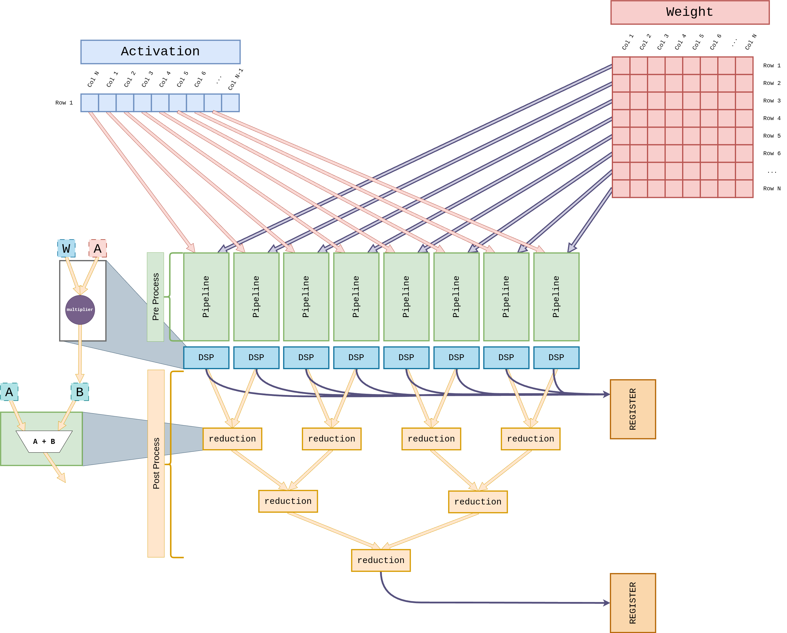
Figure 8 Figure GEMV-Core. The Pre-Process block dequantizes one
activation row and one weight column, then 32 LUT-based multipliers
compute W × A in a single cycle. The 32 partial products feed a
5-stage reduction adder tree (Stage 1: 16 DSP48E2 slices; Stages 2–5:
LUT adders) that collapses to a scalar. The Post-Process block
finally applies scale / bias and writes the result into the REGISTER.
3.1 Weight Streaming
During decoding each layer’s weights are used exactly once per token — there is no reuse. GEMV therefore uses Weight Streaming rather than Weight Stationary.
Weights stream continuously from HP2 / HP3.
They pass through the Weight Buffer into each core’s W-side Pre-Process stage.
The Weight Buffer is just a circular FIFO; no residency required.
3.2 Activation Reuse
The activation vector x lives in the L2 cache, and the four GEMV
cores broadcast the same vector among themselves.
Preload an activation tile from L2 into the per-core L1 cache.
Pre-Process dequantizes INT8 → BF16 and applies the scale.
32 LUT-based multipliers execute
W × Ain parallel in a single clock. BecauseWis INT4, the 16 possibleA × wproducts are pre-computed in the LUT; the actual weight bits only select the matching entry.
3.3 Reduction Tree
Each core’s 32 partial products collapse to a single scalar through a 5-stage adder tree, with a pipeline register between every stage for 400 MHz closure.
        flowchart TB
  MAC["32 × partial products<br/>(LUT-based W × A)"]
      --> S1["Stage 1 — DSP48E2<br/>16 × (a + b)<br/>32 → 16"]
  S1  --> S2["Stage 2 — LUT<br/>16 → 8"]
  S2  --> S3["Stage 3 — LUT<br/>8 → 4"]
  S3  --> S4["Stage 4 — LUT<br/>4 → 2"]
  S4  --> S5["Stage 5 — LUT<br/>2 → 1"]
  S5  --> OUT[/Scalar/]
Stage 1 uses the DSP48E2 A:B + C (ONE48) mode purely to add two
adjacent partial products (16 DSP slices per core). Stages 2–5 use
LUT-based adders to keep the DSP budget small. The implementation
inherits from v001’s GEMV_reduction.sv and
GEMV_reduction_branch.sv.
3.4 Accumulation & Post-Processing
The reduction result lands in a Result Accumulator and is summed with subsequent weight columns to complete a full row’s partial sum.
Post-Process applies weight-scale / activation-scale / bias.
The final INT8-requantized result goes back to either the L2 cache or the direct FIFO to the SFU.
4. Parallelization Strategy
The four GEMV cores support two parallelization modes. The ISA’s
parallel_lane (5-bit) field selects the number of active cores and
the partition axis.
Mode |
Description |
|---|---|
Row Parallelism |
Four cores each compute a different subset of output rows. The weight matrix is striped along the row axis; the activation is shared. |
Head Parallelism |
Four cores handle different Multi-Head Attention heads. Both activation (Q) and weights are partitioned along the head axis. |
5. Embedded Lookup Table
The GEMV core fuses W4 dequantization and the multiply into a single LUT pre-computation.
GEMV_generate_lut.sv(inherited from v001) produces, for each BF16 activationA, all 16 pre-computed productsA × wfor the possible INT4 weight values (-8 to +7).This runs in parallel across all 32 activation positions, so each core has 32 × 16 = 512 pre-computed products ready every clock.
When the actual weight arrives, the 4-bit pattern just indexes the LUT — the matching value flows straight into the Stage-1 accumulator DSP.
Scale factors are indexed from the Constant Cache.
6. Interaction with Softmax / Normalize
GEMV’s output is consumed mainly by two patterns.
Attention:
Q·Kᵀ→CVO_EXP/REDUCE_SUM(SFU) →V·softmax(back to GEMV)FFN projection: GEMV →
CVO_GELU/CVO_SCALE(SFU) → next GEMV
The GEMV ↔ SFU path bypasses the L2 cache via a direct FIFO, cutting round-trip latency. See SFU Core (Complex Vector Operations) for details.